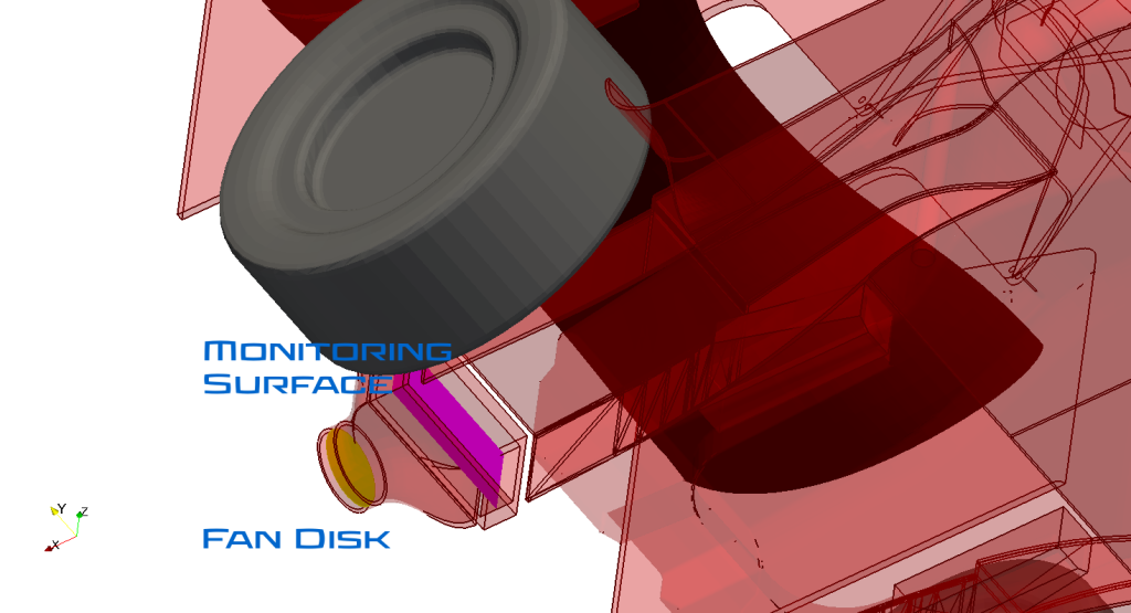
This small tutorial takes the previous tutorial about external vehicle aerodynamics one step further and introduces a radiator with a fan behind it. To keep the computational requirements reasonable the radiator is modeled with a box as a porous media. The fan is modeled as a disk using a fan curve.
The image shows an overview of the additional geometry:

There are no special requirements for the two stl files other than the box being a closed geometry and the fan disk a baffle which is a zero thickness geometry. If there are more than one radiator or fan each one should be in a separate stl file. Like other geometries these go into certain folders of the MantiumWFLow input_files/geometry folder structure. The radiators have to be placed into a folder called “porous_media” while the fan disk gets placed into “special_bc”. As MantiumWFlow can use various special geometries, it is important to use predefined name prefixes. For the fan disk shown here it is a lower case “fan_disk”. Both geometries have special physical properties which have to be specified. For this a text file with the same name as the stl file but ending with txt has to be generated. The additional folders in the input_files folder should look like this:
DP_9_MWFlow_radiator_with_fan_01
input_files
solver_settings.ini
geometry
porous_media
radiator_left.stl
radiator_left.txt
radiator_right.stl
radiator_right.txt
special_bc
fan_disk_rhs.stl
fan_disk_rhs.txt
rr_wheels
rr_wheel_lhs.stl
rr_wheel_rhs.stl
vehicle…
…
The added text file contain the physical properties of the added geometries. For the fan disk the file looks like this:
dP[Pa] v[m/s]
0, 19.6403570056
48.9519, 17.3957447764
73.42785, 16.2734386618
97.9038, 15.1511325472
122.37975, 14.0288264326
146.8557, 13.1870968466
171.33165, 11.7842142033
195.8076, 9.2590254455
244.7595, 5.611530573
293.7114, 3.6474948725
342.6633, 0
These are the values for the pressure increase over velocity. The header line is mandatory. The values are separated with a “,”. It is possible to add as many values as desired. The physical units are Pa and m/s.
The text file for the radiator looks like this:
darcey=100
forchheimer=400
e1=1,0,0
e1=0,1,0
The first two values are the Darcey-Forchheimer coefficients. These have to be calculated separately from the pressure loss data belonging to the radiator. The two next entries are vectors defining the direction of the radiator. The first one point towards the main flow direction which in this case is aligned with the X-axis. The second vector has to be orthogonal to the first vector. In this example it simply points in Y-direction.
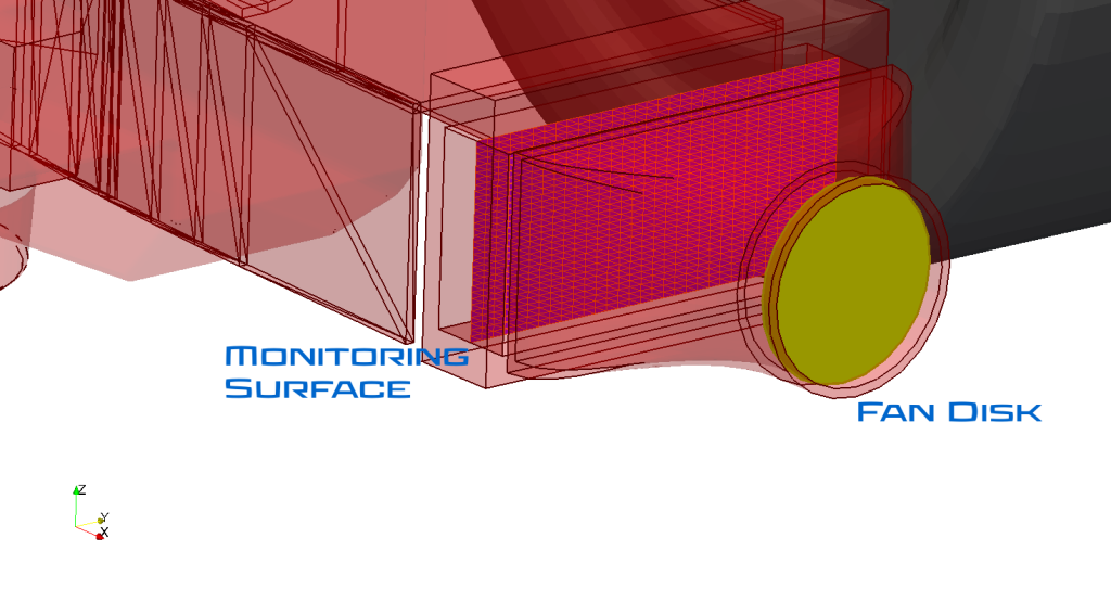
To be able to measure the flow through the radiator it is possible to add a measuring surface. It has shown that it is best to simply place a surface in the middle of the radiator as shown in the image:

This surface gets placed into a folder called “monitoring_surfaces”. So now the folder structure looks like this:
DP_9_MWFlow_radiator_with_fan_01
input_files
solver_settings.ini
geometry
monitoring_surfaces
hx_rhs_monitor.stl
porous_media
radiator_left.stl
radiator_left.txt
radiator_right.stl
radiator_right.txt
special_bc
fan_disk_rhs.stl
fan_disk_rhs.txt
rr_wheels
rr_wheel_lhs.stl
rr_wheel_rhs.stl
vehicle…
…
As this surface will not be a part of the actual CFD mesh, it is important how the stl is triangulated as the monitored flow will be monitored on the triangles of the stl file. Too large triangles will cause interpolation issues. A good rule of thumb is to have a uniform 5-10mm mesh as seen in the image:

The case can be run just like in the previous tutorial:
Windows:

MWFlow.exe ...\support_questions\DP_9_MWFlow_radiator_with_fan_01 f1_dprc
Linux: ./MWFlow .../support_questions/DP_9_MWFlow_radiator_with_fan_01 f1_dprc
To post-process the case the user can execute the post-processing utility similar to how the setup tool worked:
Windows:

MWFlow_PP.exe ...\support_questions\DP_9_MWFlow_radiator_with_fan_01
Linux: ./MWFlow_PP .../support_questions/DP_9_MWFlow_radiator_with_fan_01
This will create an html file in the postProcessing folder of the CFD case. It can be opened with any internet browser.
Additional post-processing which can be performed with Paraview by opening the case.foam file reveals that with the selected settings the fan disk adds a very moderate amount of energy to the flow. However with the settings of this simulation it is not enough to add what was lost in the heat exchanger:
