This small tutorial will show how to setup a simple external vehicle aerodynamics case in MantiumWFlow.
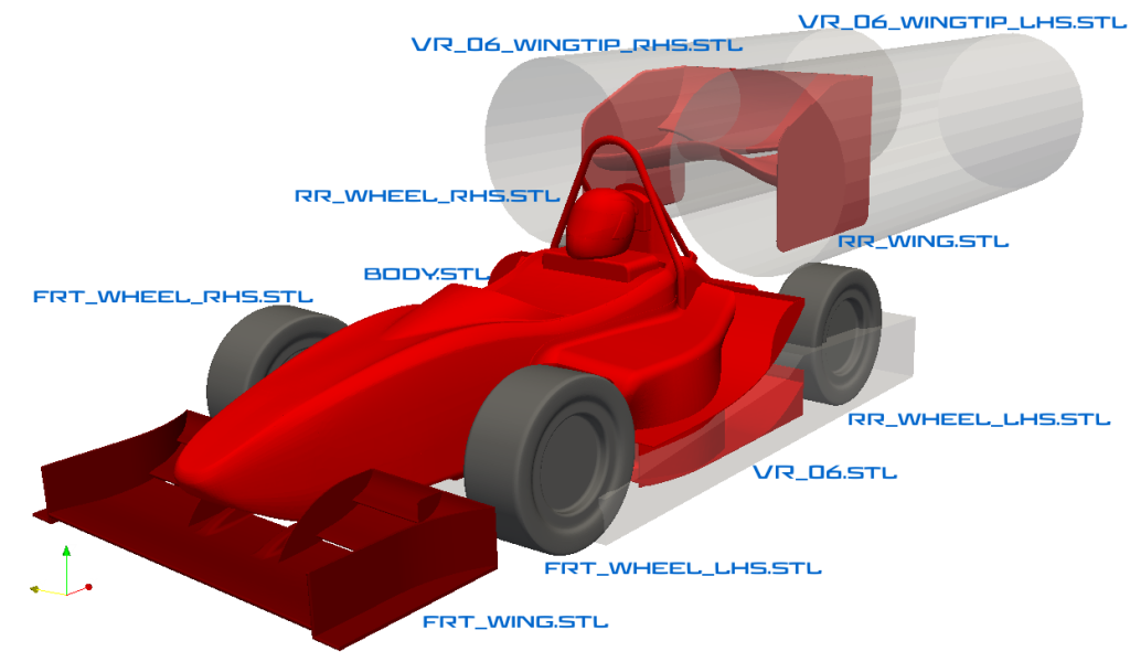
The image shows an overview of the geometry:

The car and additional geometry is prepared as stl files. The transparent volumes are so called volume refinement regions. The name is case sensitive. The number behind the “VR_” indicates how much additional refinement will be applied in these regions. The vehicle wake region is automatically refined by MantiumWFlow. In this case the floor gets additional refinement as it is very close to the ground which will affect the under body aerodynamics. As the rear wing has a very low aspect ratio, strong vertices are expected so refinement zones are added as well.
To prepare the case setup for MantiumWFlow a folder with a case name (no spaces or other strange characters like -,*,/,\, please) has to be prepared, in that folder an additional folder called “input_files” has to be created. In this folder a folder called “geometry” has to be created and optionally a text file called “solver_settings.ini”.
For this case a set of folders in the geometry folder should be created. These are:
frt_wheels
high_res_surfaces
rr_wheels
vehicle_body
vr_zones
MantiumWFlow uses this folder structure to create the CFD case. Any number of files can be dumped into these folders. Here the main vehicle body consists of one large file. It could just as well be a set of files, like: floor, driver, main_covers… This makes it easier to exchange certain parts when running many CFD simulations without having to do tedious CAD work to combine everything into one part.
The folder names are more or less self explanatory. So the user can place the stl files into the respective folders. The VR* files go into the “vr_zones folder”. As the front wing shows some delicate features and is not specially refined in this case by a VR zone it can be placed in the “high_res_surfaces” folder.
After the user is done the structure should look like this:
DP_8_MWFlow_01
input_files
solver_settings.ini
geometry
frt_wheels
frt_wheel_lhs.stl
frt_wheel_lhs.stl
high_res_surfaces
frt_wing.stl
rr_wheels
rr_wheel_lhs.stl
rr_wheel_rhs.stl
vehicle_body
body.stl
rr_wing.stl
vr_zones
VR_06.stl
VR_06_wingtip_lhs.stl
VR_06_wingtip_rhs.stl
Now MantiumWFlow can setup the case. For this the user has to using the cmd prompt in Windows or a terminal in Linux to the folder with the MantiumWFlow executable. And execute it with the Case name and the CFD template as arguments:
Windows:

MWFlow.exe ...\support_questions\DP_8\DP_8_MWFlow_01 f1_dprc
Linux: ./MWFlow .../support_questions/DP_8/DP_8_MWFlow_01 f1_dprc
Now an output like this should appear and MantiumWFlow sets up the case:
checking folder structure...
reading files...
Checking stl files...
this may take very long, depending on the size of the stls.
rr_wing
When this is done the user can go back into the case folder and execute the runCase.sh file. This will start the simulation.
To post-process the case the user can execute the post-processing utility similar to how the setup tool worked:
Windows:

MWFlow_PP.exe ...\support_questions\DP_8\DP_8_MWFlow_01
Linux: ./MWFlow_PP .../support_questions/DP_8/DP_8_MWFlow_01
This will create an html file in the postProcessing folder of the CFD case. It can be opened with any internet browser.